11.10.2 Lab – Design and Implement a VLSM Addressing Scheme (Answers)
Objectives
Part 1: Examine Network Requirements
Part 2: Design the VLSM Address Scheme
Part 3: Cable and Configure the IPv4 Network
Context / Scenario
The Variable Length Subnet Mask (VLSM) was created to prevent IP addresses from being wasted. A network is subnetted and then re-subnetted using VLSM. This procedure may be done indefinitely to establish subnets of varying sizes depending on the number of hosts necessary in each subnet. Address planning is required for effective utilization of VLSM.
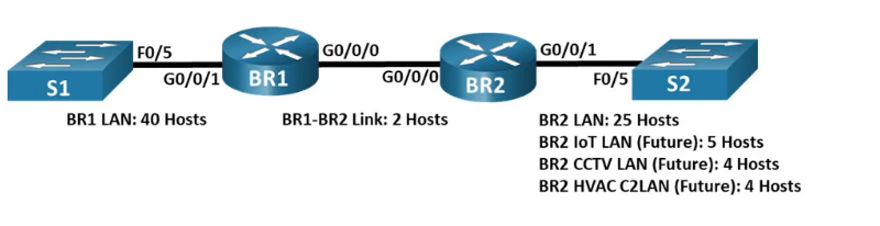
In this lab, you will utilize the network address 192.168.33.128/25 to create an address scheme for the network seen in the topology diagram. VLSM is used to address IPv4 addresses. After you've created the VLSM address scheme, you'll configure the routers' interfaces with the necessary IP address information. Addresses will need to be assigned to the future LANS at BR2, but no interfaces will be setup at this time.
Cisco 4221 routers running Cisco IOS XE Release 16.9.4 are utilised in the CCNA hands-on labs (universalk9 image). Cisco Catalyst 2960 switches running Cisco IOS Release 15.2(2) are utilised in the labs (lanbasek9 image). Other Cisco routers, switches, and Cisco IOS versions are also compatible. Depending on the model and Cisco IOS version, the available commands and output may differ from what is shown in the labs. The right interface IDs are listed in the Router Interface Summary Table at the conclusion of the experiment.
Nota bene: Ensure that the routers have been deleted and that they do not contain any startup settings. Consult your teacher if you are uncertain. Instructor Note: The processes for initialising and reloading devices are detailed in the Instructor Lab Manual. If time is a concern, this lab may be done in numerous sessions. Parts 1 and 2 are both written assignments that may be given as homework. Part 3 is a hands-on component that needs laboratory equipment.
Required Resources
- 2 Routers (Cisco 4221 with Cisco IOS XE Release 16.9.4 universal image or comparable)
- 2 Switches (Cisco 2960 with Cisco IOS Release 15.2(2) lanbasek9 image or comparable)
- 1 PCs (Windows with terminal emulation program, such as Tera Term)
- Console cables to configure the Cisco IOS devices via the console ports
- Ethernet and serial cables as shown in the topology
- Windows Calculator (optional)
Part 2: Design the VLSM Address Scheme
Step 1: Calculate the subnet information.
Use the information that you obtained in Part 1 to fill in the following table.

Step 2: Complete the device interface address table.
Assign the first host address in the subnet to the Ethernet interfaces. BR1 should be allocated the first host address in the BR1-BR2 Link.

Part 3: Cable and Configure the IPv4 Network
In Part 3, you will cable the network to match the topology and configure the three routers using the VLSM address scheme that you developed in Part 2.
Step 1: Cable the network as shown in the topology.
Step 2: Configure basic settings on each router.
a. Assign the device name to the routers.
router(config)# hostname BR1
router(config)# hostname BR2
b. Disable DNS lookup to prevent the routers from attempting to translate incorrectly entered commands as though they were hostnames.
BR1(config)# no ip domain lookup
BR2(config)# no ip domain lookup
c. Assign class as the privileged EXEC encrypted password for both routers.
BR1(config)# enable secret class
BR2(config)# enable secret class
d. Assign cisco as the console password and enable login for the routers.
BR1(config)# line con 0
BR1(config-line)# password cisco
BR1(config)# login
BR2(config)# line con 0
BR2(config-line)# password cisco
BR2(config)# login
e. Assign cisco as the VTY password and enable login for the routers.
BR1(config)# line vty 0 4
BR1(config-line)# password cisco
BR1(config-line)# login
BR2(config)# line vty 0 4
BR2(config-line)# password cisco
BR2(config-line)# login
f. Encrypt the plaintext passwords for the routers.
BR1(config)# service password-encryption
BR2(config)# service password-encryption
g. Create a banner that will warn anyone accessing the device that unauthorized access is prohibited on both routers.
BR1(config)# banner motd $ Unauthorized Access is Prohibited $
BR2(config)# banner motd $ Unauthorized Access is Prohibited $
Step 3: Configure the interfaces on each router.
a. Assign an IP address and subnet mask to each interface using the table that you completed in Part 2.
BR1(config)# interface g0/0/0
BR1(config-if)# ip address 192.168.33.249 255.255.255.252
BR1(config-if)# interface g0/0/1
BR1(config-if)# ip address 192.168.33.129 255.255.255.192
BR2(config)# interface g0/0/0
BR2(config-if)# ip address 192.168.33.250 255.255.255.252
BR2(config-if)# interface g0/0/1
BR2(config-if)# ip address 192.168.33.192 255.255.255.224
b. Configure an interface description for each interface.
BR1(config)# interface g0/0/0
BR1(config-if)# description BR1-BR2 Link
BR1(config-if)# interface g0/0/1
BR1(config-if)# description Connected to S1
BR2(config-if)# interface g0/0/0
BR2(config-if)# description BR1-BR2 Link
BR2(config-if)# interface g0/0/1
BR2(config-if)# description Connected to S2
c. Activate the interfaces
BR1(config)# interface g0/0/0
BR1(config-if)# no shutdown
BR1(config-if)# interface g0/0/1
BR1(config-if)# no shutdown
BR2(config)# interface g0/0/0
BR2(config-if)# no shutdown
BR2(config-if)# interface g0/0/1
BR2(config-if)# no shutdownStep 4: Save the configuration on all devices.
BR1# copy running-config startup-config
BR2# copy running-config startup-config
Step 5: Test Connectivity.
a. From BR1, ping BR2’s G0/0/0 interface.
b. From BR2, ping BR1’s G0/0/0 interface.
c. Troubleshoot connectivity issues if pings were not successful.
Note: Pings to the GigabitEthernet LAN interfaces on other routers will not be successful. A routing protocol needs to be in place for other devices to be aware of those subnets. The GigabitEthernet interfaces also need to be in an up/up state before a routing protocol can add the subnets to the routing table. The focus of this lab is on VLSM and configuring the interfaces.
Question of Reflection
Can you conceive of a way to calculate the network addresses of successive /30 subnets more quickly?
The responses may vary. A /30 network contains four address spaces: one for the network, two for hosts, and one for broadcast. Another way to generate the next /30 network address is to take the previous /30 network address and add 4 to the final octet.
Router Interface Summary Table

Device Configs
Router BR1 (Final Configuration)
BR1# show run
Building configuration...


Current configuration : 1558 bytes
!
version 16.9
service timestamps debug datetime msec
service timestamps log datetime msec
service password-encryption
no platform punt-keepalive disable-kernel-core
!
hostname BR1
!
boot-start-marker
boot-end-marker
!
!
vrf definition Mgmt-intf
 !
 address-family ipv4
 exit-address-family
 !
 address-family ipv6
 exit-address-family
!
enable secret 5 $1$ehVu$efQjBqXqcVcSfwLJyhwHT/
!
no aaa new-model
!
no ip domain lookup
!
subscriber templating
!
multilink bundle-name authenticated
!
spanning-tree extend system-id
!
redundancy
 mode none
!
interface GigabitEthernet0/0/0
 description BR1-BR2 Link
 ip address 192.168.33.249 255.255.255.252
 negotiation auto
!
interface GigabitEthernet0/0/1
 description Connected to S1
 ip address 192.168.33.129 255.255.255.192
 negotiation auto
!
interface Serial0/1/0
!
interface Serial0/1/1
!
interface GigabitEthernet0
 vrf forwarding Mgmt-intf
 no ip address
 shutdown
 negotiation auto
!
ip forward-protocol nd
no ip http server
no ip http secure-server
ip tftp source-interface GigabitEthernet0
!
control-plane
!
banner motd ^C Unauthorized Access is Prohibited ^C
!
line con 0
 password 7 121A0C041104
 login
 stopbits 1
line aux 0
 stopbits 1
line vty 0 4
 password 7 045802150C2E
 login
!
end
Router BR2 (Final Configuration)
BR2# show run
Building configuration...

Current configuration : 1468 bytes
!
version 16.9
service timestamps debug datetime msec
service timestamps log datetime msec
service password-encryption
no platform punt-keepalive disable-kernel-core
!
hostname BR2
!
boot-start-marker
boot-end-marker
!
vrf definition Mgmt-intf
 !
 address-family ipv4
 exit-address-family
 !
 address-family ipv6
 exit-address-family
!
enable secret 5 $1$.s3c$IJxdfZCYkvll8ifXtsW8O/
!
no aaa new-model
!
no ip domain lookup
!
subscriber templating
!
multilink bundle-name authenticated
!
spanning-tree extend system-id
!
redundancy
 mode none
!
interface GigabitEthernet0/0/0
 description BR1-BR2 Link
 ip address 192.168.33.250 255.255.255.252
 negotiation auto
!
interface GigabitEthernet0/0/1
 description Connected to S2
 ip address 192.168.33.193 255.255.255.224
 negotiation auto
!
interface Serial0/1/0
!
interface Serial0/1/1
!
interface GigabitEthernet0
 vrf forwarding Mgmt-intf
 no ip address
 shutdown
 negotiation auto
!
ip forward-protocol nd
no ip http server
no ip http secure-server
ip tftp source-interface GigabitEthernet0
!
control-plane
!
banner motd ^C Unauthorized Access is Prohibited ^C
!
line con 0
 password 7 0822455D0A16
 login
 stopbits 1
line aux 0
 stopbits 1
line vty 0 4
 password 7 070C285F4D06
 login
!
end


Comments
Post a Comment